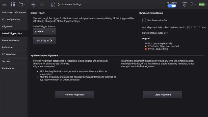
This tab brings up the Global Trigger and Synchronization menu. Synchronization is used when you need repeatable coherent phase and triggering across the channels in a multi-channel configuration. Global Trigger is used as the trigger source when channels must be synchronized.
Last Synchronization Alignment Data Collection Time
For the M9484C with Option PCH. Enables synchronization across the channels of instruments with more than one channel. Synchronization is achieved with the instrument operating at the same conditions as the last Synchronization Alignment. Synchronization is used in conjunction with the Global Trigger. When Synchronization is on, annunciation is provided to indicate the Synchronization Status.
|
GUI Location |
System Menu > Settings (gear icon) > Global Trigger/Sync > Synchronization On |
|
SCPI Command |
SYSTem:SYNChronize[:STATe] ON|OFF|1|0 SYSTem:SYNChronize[:STATe]? |
|
SCPI Example |
SYST:SYNC ON SYST:SYNC? |
|
Dependencies |
When Sync is off, the annunciator in the status line shows no text or icons. |
|
Preset |
Not reset by Preset, set to On with Restore System Settings to Defaults |
|
State Saved |
Persistent, survives preset and power cycle but not saved in the instrument state. |
|
Choices |
OFF | ON |
|
Initial S/W Revision |
A.10.00 |
Synchronization Alignment is available on M9484C with Option PCH or SNC.
Runs an internal alignment to synchronize the channels of the instrument, establishing a repeatable Global Trigger and coherent phase.
This alignment may take several minutes to perform. It must be run after power-up once the instrument is at a stable temperature. It also must be run if the frequency reference is changed between internal and external or has recovered from an unlock condition. There are situations where the alignment must be cleared before it is performed, see Clear Alignment.
|
GUI Location |
System Menu > Settings (gear icon) > Global Trigger/Sync > Perform Alignment |
|
SCPI Command |
SYSTem:SYNChronize:ALIGn? |
|
SCPI Example |
SYST:SYNC:ALIG? |
|
Notes |
Returns 0 if successful Returns 1 if failed While performing the alignment, the Aligning bit (bit 0 in the Status Operation register) is set. Completion, or termination, will clear bit 0 in the Status Operation register. This command is sequential; it must complete before further SCPI commands are processed. Interrupting the alignment from remote is accomplished by invoking Device Clear followed by the :ABORt command. This alignment can take a significant amount of time, if running alignments using SCPI, ensure your timeout is set to take this into account. |
|
Status Bits/OPC dependencies |
If the alignment fails, bit 4 in the Status Questionable Calibration register is set. |
|
Initial S/W Revision |
A.10.00 |
Synchronization Alignment Data collection occurs when a successful alignment is completed after a Clear Alignment has been performed. When this occurs a time stamp is displayed on the Synchronization screen and available with a SCPI query. If no successful alignment has occurred ‘Jan 1, 2022 1:1:1 AM‘ is displayed.
|
GUI Location |
System Menu > Settings (gear icon) > Global Trigger/Sync > Last Synchronization Alignment Data Collection Time |
|
SCPI Command |
SYSTem:SYNChronize:ALIGn:TIME? |
|
SCPI Example |
:SYST:SYNC:ALIG:TIME? |
|
Notes |
Return value is an integer list with the order of YYYY,MM,DD,HH,MM,SS. If there has been no successful Synchronization Alignment return value will be 2022,1,1,1,1,1. |
|
Status Bits/OPC dependencies |
|
|
Initial S/W Revision |
A.10.00 |
Clears the internal data of the synchronization alignment. This operation must be performed if the synchronization cabling is modified or the stable operating temperature is different from the last alignment. Clearing the alignment sets the status to Synchronization Alignment Needed.
If the Clear operation is executed with the same cabling or operating temperature, the results of the next synchronization may not match the prior synchronization. In other words, clearing the alignment precludes repeatability
|
GUI Location |
System Menu > Settings (gear icon) > Global Trigger/Sync > Clear Alignment |
|
SCPI Command |
SYSTem:SYNChronize:ALIGn:CLEar |
|
SCPI Example |
:SYST:SYNC:ALIG:CLEar |
|
Notes |
|
|
Status Bits/OPC dependencies |
Sets bit 4 in the Status Questionable Frequency register |
|
Initial S/W Revision |
A.10.00 |
The status of synchronization process.
|
GUI Location |
System Menu > Settings (gear icon) > Global Trigger/Sync > Synchronization Status |
|
SCPI Command |
SYSTem:SYNChronize:OSTatus? |
|
SCPI Example |
:SYST:SYNC:OST? |
|
Notes |
Return value is an integer: 0 = Synchronization Off 1 = Synchronized 2 = Synchronization Alignment needed 3= Synchronized out-of-temp |
|
Status Bits/OPC dependencies |
Refer to bits 4 and 5 in the Status Questionable Frequency register |
|
Initial S/W Revision |
A.10.00 |
For the M9484C with Option PCH, Global Trigger is used for repeatable triggering of channels in the instrument . For the channels you want to trigger synchronously, the individual Signals’ Trigger Source must be set to Global Trigger, see Trigger Source in the Signals Block topic.
For the M9484C with Option PCH. For all channels that are set to Global Trigger, this selection sets the source of the trigger. This is used to trigger all signals’ triggers with “Global Trigger” input in a synchronous fashion. When Global Trigger Source is set to EXTernal, the connector to use for supplying the trigger is STrig In. When Global Trigger Source is set to BUS, use the *TRG command to initiate the trigger.
Global Trigger source of Immediate initiates an internal triggering of the vector modulation when:
Any Signal’s trigger is transitioned to Global Trigger, on any channel
Any Signal is transitioned to Enable with the Signal’s trigger source set to Global Trigger, on any channel
Any Signal set to Global Trigger chooses another waveform file, on any channel
Any Signal set to Global Trigger changes settings for Frequency Offset
Any Signal set to Global Trigger when Fading is enabled or any Fading Setup setting changes while Fading is enabled
Any Signal set to Global Trigger when CW Interferer is enabled or any CW Interferer settings change while CW Interferer is enabled
Vector modulation is interrupted while the internal trigger arms and initiates.
|
GUI Location |
System Menu > Settings (gear icon) > Global Trigger/Sync > Source |
|
SCPI Command |
:SYSTem:GTRigger:SOURce IMMediate|KEY|BUS|EXTernal :SYSTem:GTRigger:SOURce? |
|
SCPI Example |
SYST:GTR:SOUR KEY SYST:GTR:SOUR? |
|
Dependencies |
Option PCH |
|
Notes |
The connector to use with selection of EXTernal is STrig In |
|
Preset |
IMM |
|
Choices |
Immediate | Key | Bus | External | |
|
State Saved |
Yes |
|
Initial S/W Revision |
A.10.00 |
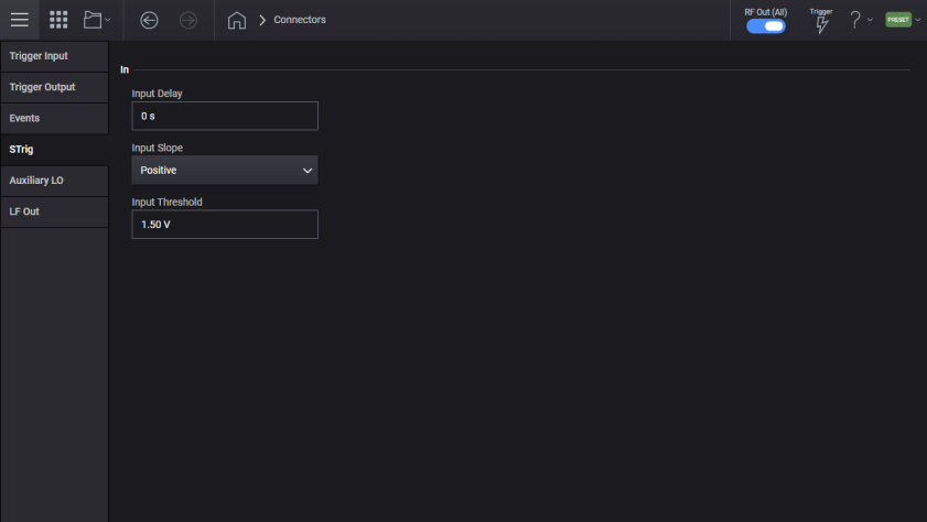
Supported on the M9484C. There is one STrig In connector for the instrument. STrig In is used in conjunction with Global Trigger.
For the M9484C there is one STrig In connector used as the External Trigger input for Global Trigger.
For the M9484C, sets the input delay at the STrig In connector.
|
GUI Location |
System Menu > Settings (gear icon) > Global Trigger/Sync > STrig In Input Delay |
|
SCPI Command |
:ROUTe[:CONNectors]:STIN:INPut:DELay <time> :ROUTe[:CONNectors]:STIN:INPut:DELay? |
|
SCPI Example |
ROUT:CONN:STIN:INP:DEL 1 US ROUT:CONN:STIN:INP:DEL? |
|
Preset |
0 s |
|
State Saved |
Yes |
|
Min |
0 s |
|
Max |
6.82 us |
|
Resolution |
10 ns |
|
Initial S/W Revision |
A.10.00 |
For the M9484C, sets the polarity of the signal input at the STrig In connector.
|
GUI Location |
System Menu > Settings (gear icon) > Global Trigger/Sync > STrig In Input Slope |
|
SCPI Command |
:ROUTe[:CONNectors]:STIN:INPut:SLOPe POSitive|NEGative :ROUTe[:CONNectors]:STIN:INPut:SLOPe? |
|
SCPI Example |
ROUT:CONN:STIN:INP:SLOP NEG ROUT:CONN:STIN:INP:SLOP? |
|
Preset |
POSitive |
|
Choices |
Negative | Positive |
|
State Saved |
Yes |
|
Initial S/W Revision |
A.10.00 |
For the M9484C, sets the logic level to specify the standard logic thresholds for determining digital high vs low. An input high must be at least 100 mV above the threshold and an input low must be at least 100 mV below this threshold.
|
GUI Location |
System Menu > Settings (gear icon) > Global Trigger/Sync > STrig In Input Threshold |
|
SCPI Command |
:ROUTe[:CONNectors][:RF<channel>]:STIN:INPut:THReshold <voltage> :ROUTe[:CONNectors][:RF<channel>]:STIN:INPut:THReshold? |
|
SCPI Example |
ROUT:CONN:RF1:STIN:INP:THR 1.5 V ROUT:CONN:RF1:STIN:INP:THR? |
|
Preset |
1.5 V |
|
State Saved |
Yes |
|
Min |
0 V |
|
Max |
3.3 V |
|
Resolution |
12.890625 mV |
|
State Saved |
Yes |
|
Initial S/W Revision |
A.10.00 |